Unified Simulation System Proposal
This is a proposal for a simulation framework for Blender. The goal is to have a unified environment to setup all kinds of simulations.
My hope is that this proposal can offer a concrete starting point for further discussion about how we want simulations to work in Blender in the future. Since this is a document about a framework and not about individual features, it will be relatively technical. It is supposed to be read by developers and technical artists.
What is a Simulation?
On an abstract level, a simulation is a function that modifies state. It
can be thought of as a function with the following signature
void simulate(state, environment, time_step).
state: Mutable container that contains the state to be modified. For example, it may contain the positions and rotations of all objects in a rigid body simulation.environment: Immutable data containing information about the outside world that the simulation runs in. Usually, that will be a partially evaluated Blender scene.time_step: A non-negative real number that represents the amount of time that should be simulated.
For example, when the simulation is started from frame zero, the calls
to simulate in every frame would look like below. This applies to
all simulations I can think of currently.
/* First Frame */
state = empty_state()
/* Use zero time step to initialize the state. */
simulate(state, initial_scene_state, 0)
...
/* Second Frame */
simulate(state, new_scene_state, 1 / fps)
...
/* Third Frame */
simulate(state, new_scene_state, 1 / fps)
The rest of the proposal mainly deals with the following questions:
- How to define the
simulatefunction using nodes? - How to integrate that node system with the rest of Blender?
Node System Design
This section describes what a node system representing arbitrary simulations can look like. First, the core concepts will be explained. Then, some syntactic sugar is introduced, that will make working with the node system more practical.
Core System
At its core, the node system has only two different socket types: State Objects and Operation.
A State Object is a container for arbitrary data. It has a (possibly nested) key-value storage, whereby the key is always a string. The value can be almost anything. The idea is to split up the *state* from the previous section into smaller state objects. Those can then be processed by nodes more easily.
By default, a state object does not have any meaning attached to it. It is just a generic data storage. However, predefined node groups will add specific data to them, that will give them meaning. For example, when a state object gets a density and velocity grid attached to it, it can be interpreted as fluid domain object. Or, when a state object gets a point cloud attached to it, it can be interpreted as particle system.
An Operation does not represent data, but a function that can be run
later. The signature of this function is
void operation(set_of_state_objects, environment, time_step).
While the *state* is split up into smaller state objects, the simulate
function from the previous section is split up into smaller operations.
An operation could also be called "solver", but I found that confusing
in some contexts.
There are only three core nodes for now: State Object, Merge and Apply Operation.
The State Object node represents a single state object, that has a unique name among all state objects used by a simulation. There is a one-to-one mapping between all the state objects used in the simulation and the State Object nodes. However, when a State Object node is in a node group, it can be instanced. In this case, it is as if the node has been copied. The name of the state object will be made unique automatically if necessary.
The Merge node performs the union of an arbitrary number of incoming state object sets and outputs the new set.
The Apply Operation node has a state object set and an operation as input. It runs the operation on the given objects and outputs the modified objects.
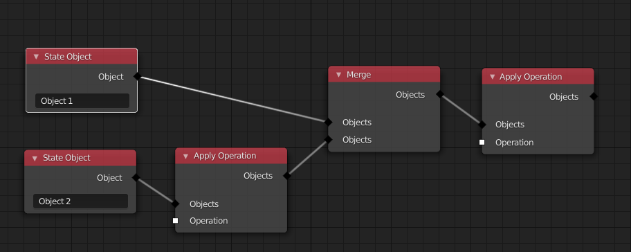
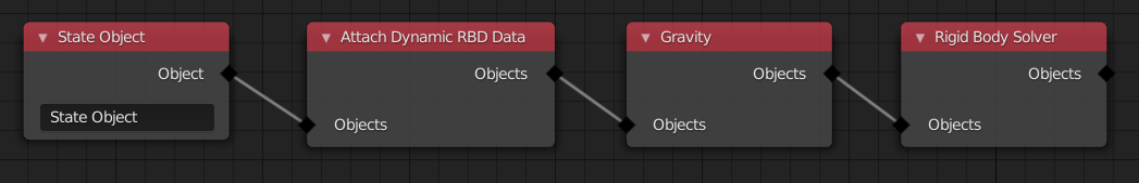
This node tree describes a simulate function, which does the
following things when executed:
- Create an empty state object for every corresponding node if it does not exist already.
- Apply an operation only on "Object 2".
- Apply an operation on both objects.
The final modified version of each state object will be the starting point for the next time step.
An operation can:
- check if a state object has certain data,
- add data to state objects,
- remove data from state objects and
- modify existing data on state objects.
The evaluation order of Apply Operation nodes is simply their order when topologically sorted. Unfortunately, there does not have to be a unique order when using toposort. When the individual Apply Operation nodes do not influence each other, that is fine.
However, in other cases, the order might affect the outcome of the simulation.
There are multiple possible ways to deal with this situation:
- Not allow this situation at all. So we could just present the user an error until it has been fixed.
- Do not define the order. So just run toposort and hope that it is what the user wants.
- Explicitly randomize the order to avoid having users depend on a certain order.
The issue with just not allowing this situation at all is that it can be useful sometimes. For example, when one state object is only passive in two separate operations, it might result in a nicer node tree, when the user does not have to define an order. Therefore, I'd currently prefer to explicitly randomize the order. However, maybe it might be better to just not allow this situation and enforce a total order of operations that could theoretically affect each other. I'm not sure yet.
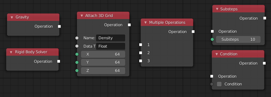
Nodes that output an operation are the ones actually doing some work. The list of possible nodes in that category is huge, but here are some examples:
- Attach 3D grid: Adds a 3d grid of specified dimensions to the state objects if it does not exist already.
- Attach Dynamic/Static Rigid Body Data: Adds data to a state object, that contains information about the mass, geometry etc.
- Rigid Body Solver: Modifies all state objects that have dynamic rigid body data attached to it.
- Multiple Operations: Has multiple operations as input, and runs them one after the other.
- Substeps: Has an operation as input. It calls this operation multiple times, with some fraction of the actual time step.
- Gravity: Attaches data that indicates to solvers, that this object should be influenced by gravity.
- Condition: Only runs the incoming operation, when a certain condition is met.
Syntactic Sugar
While the core system, as described above, provides all the flexibility we need, it is a bit verbose in some cases. Often more nodes are necessary than should be necessary. That is mainly because of the Apply Operation nodes which do not add information to the user in many cases.
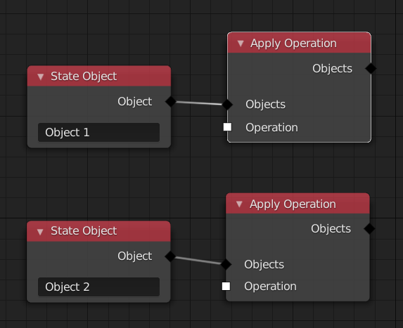
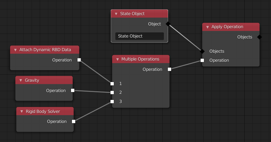
In this example, a simple rigid body simulation is setup. There is a single object that is falling down due to gravity.
In the following, two features are presented, that will make working with such node trees more practical.
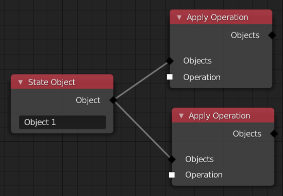
First, realize that the node tree above can also be represented like this:
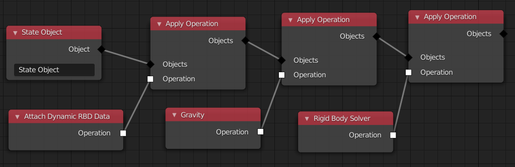
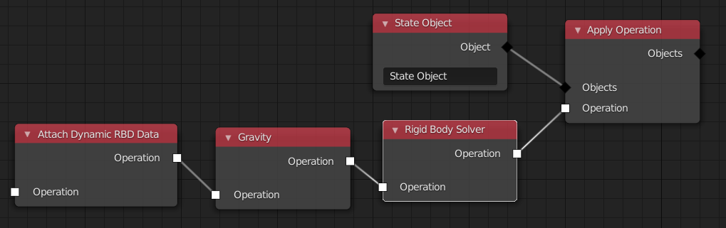
The goal of the first syntactic sugar feature is to eliminate the need for the Multiple Operations node in many cases. We can do this by giving every node, that outputs an operation, an operation input. The semantic is that the incoming operation is performed before the one of the current node. That changes the node tree to look like so:
The goal of the second feature is to reduce the number of necessary Apply Operation nodes. This can be done by making the Operation input and output sockets in some nodes more dynamic. For example, when the Gravity node has an operation as input, its output will also be an operation. However, when the input is a set of state objects, the output will be the same set of state objects. The semantic is, that this operation will be applied on the objects that pass through it. This results in a much cleaner node tree.
Integration in Blender
Now, that we have a way to represent arbitrary simulations with a node system, it is time to think about how this can be integrated into Blender.
This chapter will propose answers to the following questions:
- Where will the simulation node tree be stored in DNA?
- How can the simulation depend on objects?
- How can objects depend on the output of a simulation?
Simulation as Object Type
A solution that seems to work quite well in many regards is to introduce a new object type (like mesh, curve, etc.) for simulations. The simulation data attached to simulation objects is first and foremost the node tree, but possibly also other properties.
In the viewport this object can be used to visualize data from the state objects in the simulation. The user can choose which data from which state object is drawn. That can include e.g. velocity fields, particle positions, etc. It might be useful, to display these things in a final render as well, but there are better solutions for that.
The location of the simulation object does not influence the simulation itself. It just changes where in the viewport the simulation data is visualized.
By having simulations as normal object, they can be integrated into the depsgraph fairly naturally. The simulation step is performed as part of the depsgraph evaluation. All the state objects in the simulation are stored as run-time data on the evaluated object, until it is cached.
The simulation step will be represented as a single node in the depsgraph. In the next two sections, I'll show how this node is linked up with other depsgraph nodes.
Simulation depending on Objects
In most simulations, some data from other objects have to be imported into the simulation. For example, for a rigid body simulation, the geometry of the individual objects has to be imported into the simulation. Or, the position of an attract force is the position of some other object.
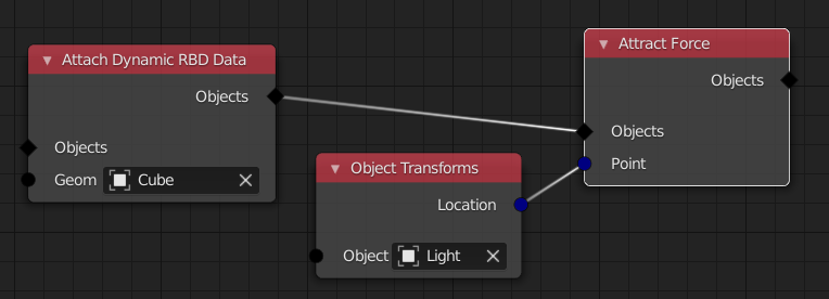
In both of these cases, an appropriate link is inserted in the depsgraph. For that to work, the dependencies have to be known statically. That means, we have to be able to extract all the dependencies from the node tree, before actually running the simulation. I'm confident that this is possible when we are careful about what kinds of nodes we allow.
Objects depending on Simulations
There are many use cases for having objects depend on simulation objects. For example, a mesh object might have a modifier that imports all points of a particle system from a simulation and does further processing. Another more complex example is when there is an animated character, where some bones are simulated. For that to work, the depsgraph has to be granular enough, but I think that should work. Furthermore, a simulation can depend on another simulation object.
In general, when some part of an object depends on a simulation, it has to specify a data path into the state objects. This is similar to how data paths are used when setting up drivers. The data path includes the name of a state object in the simulation and the name of the actual data in this object. Remember, a state object is just a key-value mapping with strings as keys.
Linking
In the examples that I thought about so far, this approach of having a simulation object type seems to work quite naturally with linking. When a simulation is linked, all objects the simulation needs are linked as well. When an object is linked, that depends on a simulation, that simulation will be loaded as well.
Simulation Caching
Simulations are cached at the simulation object level. The result of each simulation step is a set of state objects. To cache those, we "just" have to store a copy of them.
To be able to store this run-time data in a file, the values in each state objects key-value map have to be serializable. There are two main ways this can be enforced. Either, every value has to come with functions to serialize and deserialize it, or we require these values to be somehow "simple", so that a generic function can convert everything into a byte stream.
Once a simulation is cached, it will not have any incoming links in the depsgraph anymore. The objects depending on the simulation will just read from the cached state objects.
The data format for this kind of cache will probably be specific to Blender. Caches that should be interchanged with other software should be done based on e.g. a mesh object that imports data from a simulation object.