From BlenderWiki
Tutorial on flame-based fire simulation
This tutorial is aimed at explaining the process of setting up, simulating and rendering a fire simulation using the Flame based fire simulation.
WIP
The flame simulation system is work-in-progress and likely to change in several aspects. See the TODO list for details.
--Phonybone 15:09, 20 March 2010 (UTC)
|
Setting up the particle system
The flame simulation uses a particle system as the basis for flame emission. Each particle in a Fire system emits one flame.
 |  |
Create an emitter object
The emitter object should resemble the ignited area of the burning object. In many cases you can use the object itself as the emitter of particles, but often it is a good idea to create a separate object with a similar shape for several reasons:
- Vertex groups can be used to fine-tune the particle density. The visible mesh may not have a suitable, even distribution of vertices.
- A high-poly mesh might decrease performance of particle emission unnecessarily.
- A large number of burning objects can use the same emitter mesh to avoid having to set up the render volume over and over again (see #Rendering)
To avoid rendering the separate emitter object, disable the Emitter checkbox in the Render settings panel.
Particle system type
Set the particle system type to Fire (see Image 2)
Particle amount
The amount of particles in the flame simulation is usually much lower than in a standard particle application. The reason is that the particles are merely emission points for flames, which are of considerable size themselves. You may need to correct the particle amount after setting the geometry parameters (see #Flame geometry)
Display settings
 |  |
In order to get a good representation of the simulated flames, you can change the settings in the Display settings panel. There are 2 display modes available:
- Shapes
- This shows the flame shapes as approximate 3D meshes.
- Filaments
- This shows flames as simple curves.
- Use Flame Resolution to set the amount of interpolation steps of the display meshes. This can be reduced to improve the realtime display performance if you need to display a lot of flames. Note that this value should not be lower than the number of control points or your realtime display will not show enough detail. 2 to 4 times the number of control points is usually a good choice.
- The 3D meshes to not display flame turbulence, which is only visible in the final rendered image (see #Turbulence).
- Filaments does not show flame sizes or shapes, but it is more efficient than the Shapes display mode, which makes it an alternative for realtime display in case you have a large amount of flames in your simulation.
Adjust parameters
| Realtime adjustments | |
| Most changes to the simulation parameters require a recalculation of the particle system. Instead of restarting manually after each change, it is often useful to start the realtime animation in the 3D view and slowly change the sliders to get feedback on the settings! |

There are a couple of presets for different fire types to give users a good starting point for the parameters. If you are happy with the result or want to get a rendered image right away, you can skip to #Rendering
Flame geometry
- Set an appropriate flame size.
The flame size parameter describes the width of flames. The desired size will depend on the general scale of your scene and the type of fire you want to create (e.g. a candle flame is smaller than campfire flames). The Random parameter can be used to vary the flame size (0 = all flames have the same width). - Set an appropriate flame height.
This also depends on you scene scale and the amount of fuel the burning material provides (e.g. flames from burning wood are shorter than gasoline flames). Note that the flame height only defines the average length the flames reach before splitting/flickering back, so you should adjust this based on the visual result instead of the plain scene geometry! - Adjust the number of control points if necessary.
This allows more detail on the overall shape of flames, but higher numbers can decrease performance. The default value is sufficient for most situations, but you may need to increase it for very long flames.
Physics
- Tweak buoyancy:
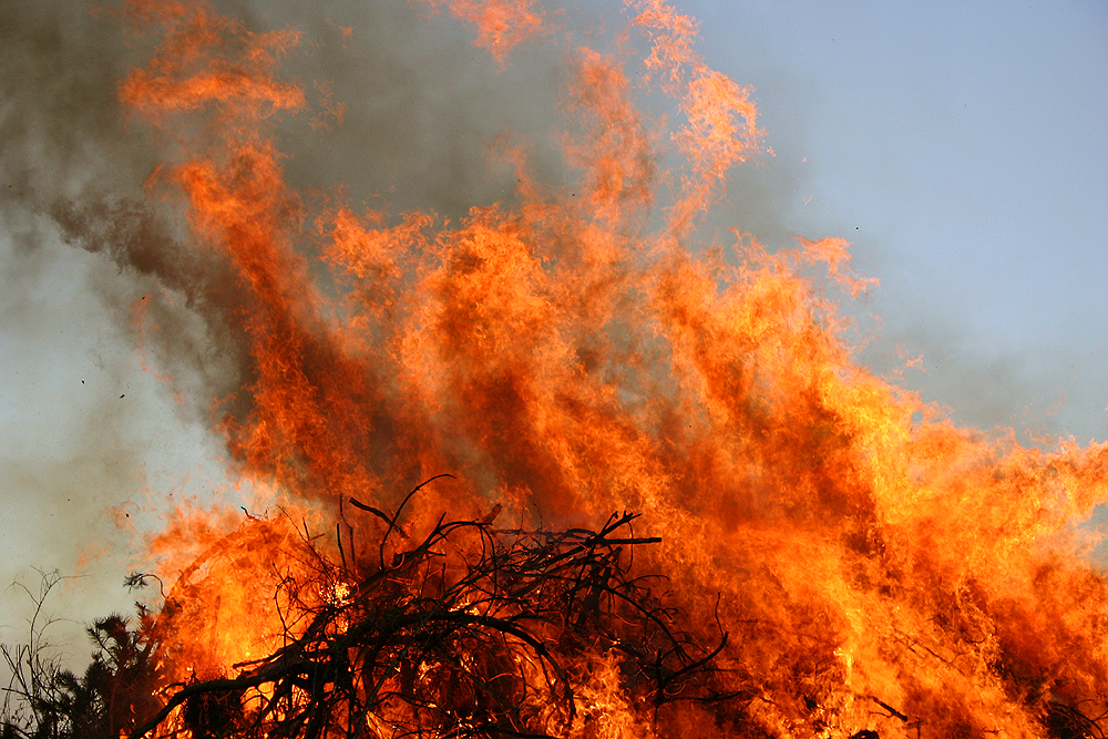
Buoyancy describes the speed with which flames rise due to heat. Flame temperature is not used in the simulation, instead the artist can set the velocity in this straight-forward manner. This effect is also proportional to the scene gravity. - Flame splitting:
When flames reach the maximum flame height, the top part can be split off and rise in the heat (see this image for a real fire showing the effect).- The split ratio parameter controls which part of the flame is split off.
- In order to smoothly blend between the flame before and after splitting, the reduced main flame and the split part overlap a certain amount. This can be tweaked by the split overlap parameter and should be adjusted to the flame shape (see #Flame Shape).
Rendering
Rendering the flames is done using a volumetric material. The flame density and color is retrieved from the particle system data using a special texture.
Render methods
Volumetric rendering is currently the only supported way. However, volume rendering can take a long time, especially for large scale scenes. Therefore additional simplified rendering methods like billboards may be implemented in the future.
|
Render geometry
In order to get a rendered image from the flame particle data, you need to create a separate mesh object that encloses the flame region. This can be a simple cube, but any other mesh will also do. This is what you should keep in mind:
- The render mesh should enclose the whole flame area.
- You can use the Shapes display mode to get an idea of what area the render mesh should cover. Note however that the actual render mesh must be a bit larger than the flame shapes in order to account for the fading density and turbulence outside the basic flame shape!
- Making the render mesh too big can decrease performance (empty space also has to be evaluated by the volumetric renderer). Try to avoid covering non-burning regions. If necessary subdivide the volume to enclose only those areas that actually contain flames (see images 4a/b/c).
 |  |  |
Volumetric material
Emissive volumetric material
The settings described in this section can be applied to any emissive volumetric material and are not specific to the flame simulation. You can also use different settings to create a different visual effect.
|

- Add a material to the render mesh and set its type to Volume
- Set Density to 0. All density will be provided by a texture, so the render mesh should not add any density itself.
- Set Emission color to black. This will also be provided by the texture.
- Set Scattering and Reflection to 0. Fire is basically a fully emissive "material", which means that scattering and reflection are negligible compared to the emitted light.
- Increase Emission to some value > 0. You may need to experiment with this setting later in order to get a good overexposure effect. It is advisable to use a value < 1 to avoid full color saturation (see #Compositing on how to achieve the final fiery look).
- Since we don't use scattering or reflection, you can set the Lighting mode to Shadeless, which might speed up rendering.
- Optional: The Transparency option can be set to Raytrace. It seems like Z Transparency has problems rendering volumetric materials with a default background.
Texture

The flame simulation introduces a new special texture to access the flame data and provide density and color information to the material. This texture works very similar to point density and voxel data textures.
- Go to the texture tab and add Particle Fire texture to the render mesh.
- Select the simulation source:
- Set the particle emitter object in the Object selection box.
- Select the particle system in the System selection box.
- Set the coordinates to World. This ensures the flames show up in the correct location:
- Select World Space from the dropdown box below Object.
- Select Global in the Coordinates dropdown box in the Mapping panel.
- Enable Density and Emission Color checkboxes in the Influence panel. This allows the texture to define the density and color values of the fire for the material.
- Set the Blend mode to Add.
- Use the color band in the Particle Fire panel to define the flame color. The right-most value is used for the highest density. Note that it is best to use fully saturated colors here instead of trying to achieve an overexposed, bright-white color seen in real fire by these colors. This effect is done best by compositing (see #Compositing).
Turbulence
Turbulence is a crucial feature of realistic fire simulation. The flame simulation uses generic turbulence functions to produce this visual effect. This is not as realistic as turbulence that is generated by fluid solvers or particle simulations, but it can fool the human eye well enough to create believable fire. The main advantage of this method is it's great performance, since it can be calculated locally without the need of a costly precalculation.
There are two different types of turbulence applied to the flame texture:
- Air turbulence
- The whirling motion of air and hot gas, which disturbs the regular basic flame shape.
- Combustion noise
- The combustion at the flame base usually varies in time and produces irregularities in the flame density, which rise with the burning gas.
Both effects can be tuned independently and should be adjusted to the type of fire that is intended. In general flames that rise slowly (due to lower temperature) will experience more air turbulence than very hot flames, e.g. campfire vs. gas burner. Also solid fuel (e.g. wood) will create more flow turbulence than liquid or gaseous fuels. In the end it is up to the artist to choose the right amount of turbulence for the targeted visual result and requires some tweaking. The fire presets can be used for a starting point.

You can access turbulence parameters in the Render panel in the Particles tab (see image 7).
- Amount: The general strength of the turbulence. Causes a displacement of the density in terms of Size. 0 means no turbulence at all. Usually values from 0.1 to 0.5 are sufficient.
- Size: Size of the largest turbulence eddies ("whirls"). Smaller eddies will be created if Depth is > 1.
- Depth: Adds additional detail at smaller scales. Note that large values can slightly decrease rendering performance.
- Variation Speed: Changes the turbulence over time to create a more realistic physical effect. 0 means the turbulence will be static.
Combustion noise only:
- Stretch: Used to create a better looking combustion noise by scaling along the flame (This will be replaced!).
Compositing
In order to create the visual overexposure effect caused by bright incandescent gas, a compositing effect can be used with the rendered fire. In order to apply this effect only to the fire and not the rest of the scene geometry, the render mesh should be put into a separate render layer. The compositing can then only affect the fire and combine with the other results afterwards.
